Many years ago in 1987, I remember being in a local shopping mall not far from where we lived. This shopping mall was to me a very special place for one very specific reason, it had an arcade room full of arcade machines. I could stay there for hours and hours at a time, not really playing a lot, but mostly looking at others playing. I was always saving up money for some new NES game in those days, so I had to be carefull… One day I remember a large crowd of people gathered around a new game that I hadn’t seen before. This game blew everything I’ve ever seen out of the water. The graphics were just amazing! I remember staying there just starring at the demo play in an endless loop, over and over again. I just couldn’t get enough of it. I was hooked. Little did I know back then that I would be owning this very arcade game, 31 years into the future. Well, a broken PCB board that is… or an “untested” board as they like to call it on ebay 🙂 This is the story of my first jamma pcb repair job.
I always wanted to get the original jamma board for this game, but the prices on ebay for a working Salamander board is today close to madness. You would probably need to shell out between 1,000 to 1,500 USD for a working board. That’s pretty insane for a 32 year old board. There are also no guarantees that the board will actually work when you receive it. It might not survive the journey. My options then was to look out for a non-working/untested board, and after looking for several months one finally showed up, and I bought it. There was only one slight problem, or a quite big one actually. I don’t have a background in electronics so I had to learn everything as I went along. It’s been a long journey, but it’s definitely been worth it.
The Konami Salamander was released in 1986 and was actually a spin-off off the famous Gradius game. In the US the game was released under the name Life-Force and had some changes compared to the Japanese and European version.

The game itself consists of two PCB boards, the top board (GX587) contains the main Motorola 68000 CPU, EPROMs, Mask ROMs, RAM for the main game logic, and a Z80 CPU for handling the music and SFX in the game. There’s also a special Sanyo VLM5030 that mimics human speech plus several custom Konami ICs. The base board (GX400) contains all the logic for dealing with the GFXs like sprites,fonts and backgrounds.

There’s also a known weakness with these boards. Rumor has it that Fujitsu, one of the big Japanese chip manufacturers in the mid-eighties, had some issues with the production quality. It’s quite common for these ICs to simply stop working, and these boards are full of them. So, maybe not the best starting point for someone like me without the required skill set. OK, enough background talk. Let’s start…
The first thing I started with was to perform a visual inspection of both boards on both sides. The boards were quite clean and seemed to be in great shape at first sight. However, after looking a bit closer not everything was quite right. The first thing that caught my attention was a missing capacitor on the base board.

It looked like it had been ripped straight off the PCB. Only the remains of the two legs could be seen. This was an easy fix, and a new one was quickly soldered back. I’d also gathered several high resolution images of the boards from different places online to compare them with my own boards. Then something struck me. Two of the EPROMs seemed to be wrong; Top board (18B & 18C). They were labeled L02 and L05. This board is a Salamander D-Set board and the EPROMs should be D02 and D05. The ‘L’ EPROMs are for the US version of Life-Force. It looked like someone had attempted to convert the board at some point. However, that will only work if the mask ROMs are also replaced with the appropriate versions. I took them out and dumped them with my EPROM reader, and the SHA256 matched the US Life-Force version. I then made two new ones with the correct ‘D-Set’ content and put them back into the board. I then decided to dump the rest of the EPROMs and mask ROMs on the board. Everything matched the D-Set except for one mask ROM that was completely dead. The problem with these mask ROMs is that they are not so easy to replace. It’s a 1Mbit 28-pin DIP ROM. A 1Mbit EPROM requires a separate pin for the programming voltage, however this requires more that 28-pins in total. This Konami ROM (TC531000) is like a normal 27C512 except that the programming pin is actually A16 on the RC531000. The best solution here would be to use a different 1Mbit EEPROM and solder it to an adapter PCB. After digging around online I found that someone had already made a PCB board for this specific use-case (Here). I ordered the needed components and made my own replica.

Now all the EPROMs and ROMs were correct! It was about time to power the board for the first time. I gently connected the Jamma harness to the board and turned on the power…… nothing. The screen was completely black and there was no sign of life. If I turned up the volume on my speakers I could hear a clicking sound like tree times per second. This told me that the board was watchdogging, meaning that the watchdog circuit was not happy with situation and was constantly resetting the CPU. Looking at the CPU reset pin of the M68K on my oscilloscope confirmed this. After some time i suddenly heard a loud laser beam sound coming from my speakers. I almost fell of my chair as I was not expecting this to happen 🙂 This led me to believe that the CPU was probably running some random opcodes since it’s behavior was non-consistent. I then started to check all 74LS244+245 buffers connected to the CPU’s address- and data-bus. This revealed that A6 was floating. A closer inspection of the board revealed that someone had soldered out the original CPU and inserted a 64-pin socket, however they had destroyed the A6 trace in the process. I repaired the trace with a small piece of wire, and powered up the board once again…. nothing! The board was still watchdogging, however there were no laser cannons firing at me 🙂 I then started to go over the board with my logical probe and check for any abnormalities. This was a tough job since I didn’t have any experience, so I wasn’t really sure what was normal or not. After spending several evenings without any progress I realized that I needed to come up with a new approach on how to tackle this problem. I needed to find out what the CPU was doing and why it got reset by the watchdog. I had a cheap logical analyzer lying around that I’d bought on ebay a year ago that I hooked up to the CPU pins.

However, it only had eight channels so there was no way I would be able to see the entire data and address bus on the M68K CPU at the same time. I therefor picked some of the CPU control pins to see if they would give me something, and they did! The CPU appeared to be executing the same opcodes over and over. However, after the fourth write instruction the /DTACK (data acknowledge) pin was not triggered, and this would just halt the CPU until the watchdog  signaled the reset pin again. So, I needed to find out what the forth write instruction was trying to access. But how would I do that? I ran the game in the MAME debugger! 🙂
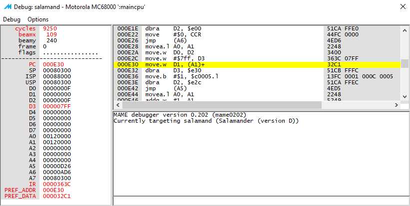
Yes! The CPU was trying to write to 0x120000. That means that both A20 and A17 will be high. I then remembered seeing something related to A20 on the schematics. As you can see the A20 line goes into the 73LS153 multiplexer and decides which of the inputs that should go to the /DTACK pin. A20+A17 high would mean that the /DTACK should be taken from input pin 1C2.
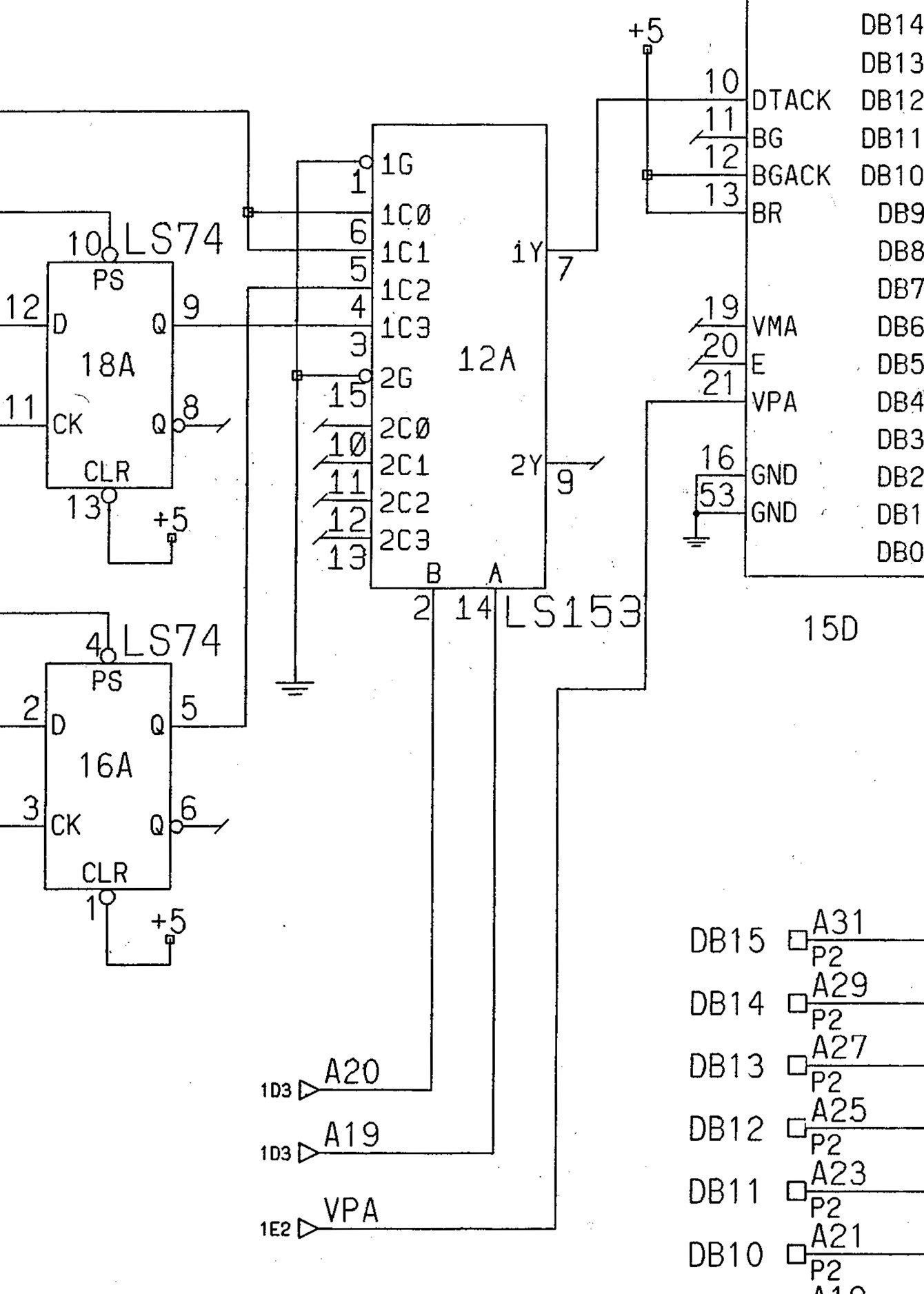
However, my oscilloscope revealed that there was no activity there. I then followed the path back to another LS244 (19A). Here the output pin was stuck high. I replaced it and then…. Something! Now the game finally booted and it actually ran stable without any resets etc. However, the sprites were all messed up. For some reason this was not consistent. Sometimes I would get different results by just resetting the game. It was random which sprites were corrupt for every reset. I was now stuck for days without any progress. I probed every chip on the video board to see if I could spot anything unusual. However, I was getting blind and running around in circles.

I couldn’t find anything wrong anywhere. Still, I would not give up on this now. Admitting defeat was not an option. I had to continue. Then, luckily I decided to do a full continuity test of all the 100 signals going from the top board to the base board across the two 25 pin ribbon cables. When I got to pin 49 on connector A I found something. The pin didn’t seem to be completely connected. I de-soldered the pin on the bottom of the PCB and discovered that the pin had actually snapped

inside the connector! The purpose of this signal was to delay the /DTACK for sprite updates. Without it, the M68K would drive the busses too fast corrupting the sprite data in transfer, this would explain the symtoms I was seeing perfectly. I didn’t have spare one so I just soldered a wire between the two boards as a quick hack. And finally, Success! The game now ran without any issues! I could hardly believe it. I had been working on this project now for almost two months and seeing the end result was almost magic.
The evil salamander was beaten once again… That’s all for now folks!

Very nice log! I really enjoy your writing style };-P
The same to you too! I did stumble upon your Bubble Bobble bootleg redux page some time ago. Definitely valuable information!
-Eicar
Really helpful blog, I have a noob question, I found a Salamander 2 pcb, noticed that the B board is missing 3 capacitors just like the legs you show on yours, however, I can’t see any issue on the gameplay, checked pcb pictures and seems like those caps are always there so, the question is, should I be worried about it? Why does it work fine? I know is a simple replacement.
Hello there! This is my first visit to your blog! We are a team of volunteers
and starting a new initiative in a community in the same niche.
Your blog provided us valuable information to
work on. You have done a marvellous job!
Howdy! This blog post could not be written any better!
Reading through this post reminds me of my previous roommate!
He continually kept talking about this. I will send this article to him.
Pretty sure he’ll have a great read. Thank you for sharing!
I think this is one of the most vital info for me.
And i am glad reading your article. But should remark
on some general things, The web site style
is perfect, the articles is really excellent :
D. Good job, cheers
Can I simply say what a relief to find someone who really
understands what they’re discussing on the internet.
You actually realize how to bring a problem
to light and make it important. More people need
to look at this and understand this side of the story.
It’s surprising you’re not more popular because you
most certainly have the gift.
I am regular visitor, how are you everybody? This article
posted at this site is genuinely good.
It’s actually a nice and useful piece of info.
I’m satisfied that you shared this useful info with us.
Please stay us informed like this. Thank you for sharing.